





ISO 13855 is an international standard that specifies how to calculate the minimum safety distance between protective devices, such as light curtains and safety sensors, and hazardous areas of machinery, based on the approach speed of the human body. It is one of the fundamental standards used when designing safety systems for presses, cutting machines, industrial robots, and many other types of production equipment. This article explains the core requirements of ISO 13855 and the role that Computer Vision (AI Cameras) can play in modern machinery safety applications.
What Is ISO 13855?
ISO 13855 (full title: Safety of machinery — Positioning of safeguards with respect to the approach speeds of parts of the human body) is an international machinery safety standard that specifies how protective devices should be positioned so that a machine can stop before any part of a person’s body can reach the hazardous area.
In Vietnam, the equivalent adopted standard is TCVN 7386:2011 (ISO 13855:2010) – Safety of machinery — Positioning of safeguards with respect to the approach speeds of parts of the human body, which belongs to the group of machinery safety standards issued by the Ministry of Science and Technology.
This standard primarily applies to electro-sensitive protective equipment, such as light curtains, safety laser scanners, and similar presence-detection devices.
Safety Distance Calculation According to ISO 13855
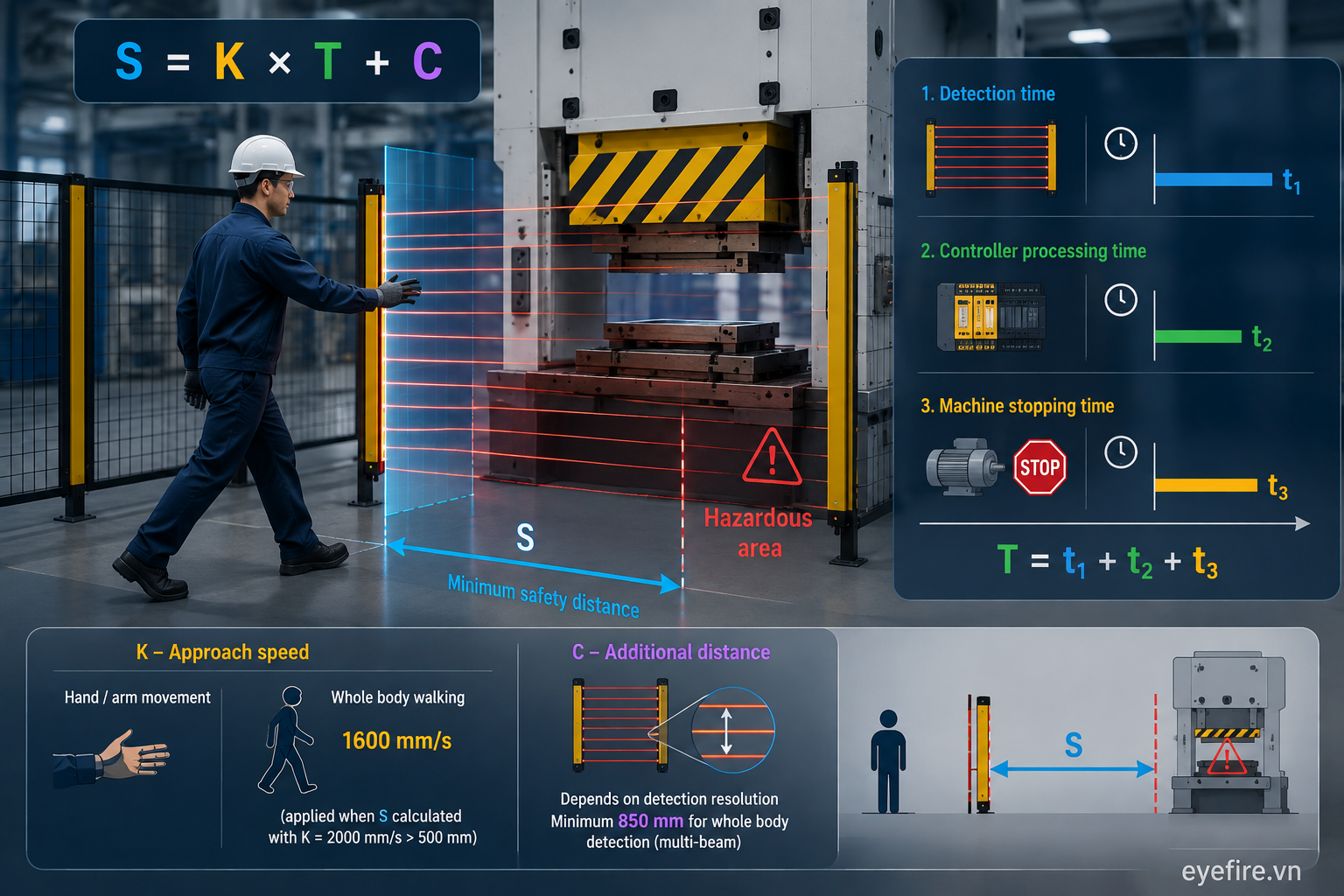
The general formula specified in ISO 13855 is S = K × T + C, where S is the minimum safety distance, K is the approach speed, T is the total stopping time of the system, and C is an additional distance based on the detection capability of the protective device.
-
S - The minimum distance (mm) from the detection zone of the protective device to the hazardous area.
-
K - The assumed approach speed of the human body. The standard specifies two commonly used values: 2000 mm/s for hand/arm movement and 1600 mm/s for whole-body walking speed (applied when the distance calculated using K = 2000 mm/s exceeds 500 mm).
-
T - The total system response time, including the time required for the protective device to detect a signal, the processing time of the safety controller, and the time required for the machine to come to a complete stop.
-
C - An additional distance that depends on the detection resolution of the device, such as the spacing between beams in a light curtain. For whole-body detection using multiple beams, C is typically set to a minimum of 850 mm to compensate for arm reach.
In other words, the slower the protective device responds or the longer the machine takes to stop, the farther the protective device must be installed from the hazardous area.
How Is ISO 13855 Related to Other Factory Safety Standards?
ISO 13855 is commonly used together with ISO 13857 (static geometric safety distances to prevent access to hazardous areas), ISO 13849-1 (design of safety-related control systems), and IEC 61496 (technical requirements for electro-sensitive protective equipment).
A common mistake is using ISO 13857 to calculate safety distances based on approach speed. In practice, ISO 13857 only specifies static geometric distances, such as openings in protective fences, whereas ISO 13855 is specifically intended for active protective devices with response times, such as light curtains and laser scanners. The safety level (PL/SIL) of the controller under ISO 13849-1 also directly affects the response time T used in the formula above.
What Challenges Arise When Applying ISO 13855 in Practice?
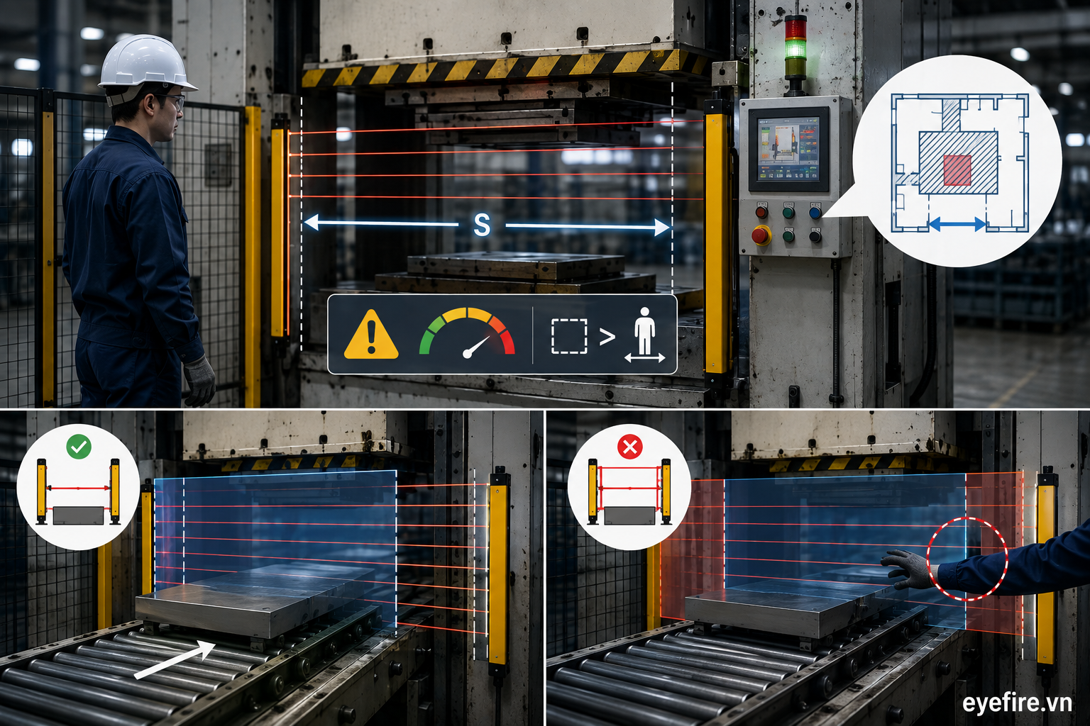
Compliance with the safety distances specified by ISO 13855 can sometimes reduce operational convenience or require factories to use additional muting mechanisms to maintain productivity.
For many production lines with limited floor space, the distance S calculated using the formula may be greater than the ideal working space available. When materials need to pass through the protected area of a light curtain during operation, factories often have to use a muting mechanism, which temporarily disables the detection zone to allow materials to pass through. If the muting window is configured incorrectly or extended to increase production speed, practical gaps may appear in the protected area even though the system still complies with the originally calculated safety distance.
Another limitation is that devices covered by ISO 13855 typically detect intrusion across a fixed plane and cannot distinguish between a person’s hand and materials unless a separate processing mechanism is implemented.
What Role Does Computer Vision Play in Machinery Safety?
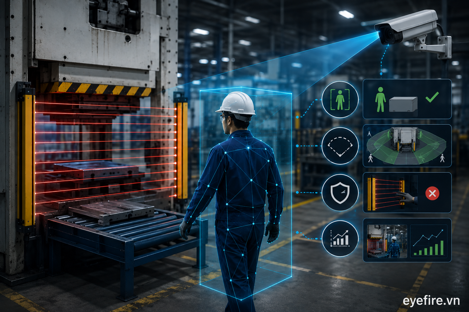
Computer Vision (AI Cameras) can add an intelligent detection layer alongside protective devices compliant with ISO 13855, helping distinguish people from materials, expand the monitored area, and provide data for safety analysis. However, it generally does not directly replace the certified machine-stopping function of these devices unless the Computer Vision system itself is certified according to the relevant safety standards.
Distinguishing People from Materials
Light curtains and other sensors used under ISO 13855 treat all objects crossing the detection zone in the same way, which means muting mechanisms are required when materials need to pass through. AI Cameras analyze object shapes and can distinguish human hands or bodies from workpieces and materials, helping reduce the need for muting in many situations and allowing the protected area to remain continuously active for longer periods.
Expanding the Monitoring Area
Devices used under ISO 13855 typically protect a single plane or approach direction. A camera can simultaneously monitor multiple approach angles, helping detect people approaching from the side or rear - directions that a standard light curtain may not cover.
Reducing the Risk of Bypassing
In production environments where there is strong pressure to maintain productivity, light curtain sensors may be covered or otherwise bypassed to avoid interrupting operations. AI Cameras do not rely on physical light beams and are therefore more difficult to disable in the same way. They can also retain images when interference or bypassing behavior is detected.
Providing Data for Safety Management
Devices used under ISO 13855 primarily generate immediate machine-stop signals without recording the context surrounding an event. AI Cameras can capture images whenever a risk is detected, allowing HSE teams to analyze near-miss incidents and continuously improve safety procedures over time.
Can Computer Vision Replace ISO 13855-Compliant Protective Devices?
No, unless the Computer Vision system is designed and certified to meet the corresponding safety level, such as Type 4, PLe, or SIL3, under the relevant standards.
Type 4 light curtains compliant with IEC 61496, combined with safety controllers meeting PLe/SIL3 requirements under ISO 13849-1, have undergone rigorous testing for reliability and response time. These characteristics provide the basis for calculating safety distances according to ISO 13855. A conventional AI Camera system that has not been certified under the corresponding functional safety standards should therefore not be considered an independent, certified machine-stopping device.
For this reason, the recommended approach is to build a multi-layered protection system: certified safety devices perform the emergency machine-stopping function in accordance with applicable standards, while AI Cameras serve as an additional monitoring layer—providing early detection, reducing false alarms, expanding the monitored area, and supplying data for safety management.
Where Should Businesses Start When Integrating Computer Vision into Existing Safety Systems?
Before adding AI Cameras, businesses should review whether their existing protective systems comply with the safety distances required by ISO 13855, particularly at locations where muting mechanisms are being used or where false alarms occur frequently. These are often the areas where an additional Computer Vision monitoring layer can provide the greatest value—not by replacing certified protective devices, but by reducing the gaps created by muting mechanisms or geometric blind spots.
The next step is to clearly define the role of AI Cameras within the safety architecture: whether the system will only issue alerts and record data, or whether detection signals will be integrated into the machine-stopping chain through the existing safety controller. This choice determines which additional certification or verification requirements the system may need to meet and should be considered together with the factory’s engineering team and safety consultants from the design stage.
EYEFIRE can support assessments of existing protective systems at individual production locations and recommend suitable AI Camera installation positions and configurations based on the characteristics of each production line—as an additional layer operating alongside existing certified protective devices, without changing the core safety architecture already established by the factory.